The 6847 Video Display Generator is the original component. It is like the 6845 but much simpler in some respects - display modes are controlled by pins not registers, and there are fewer modes. Pixel shift registers are on-chip, making it easy to use.
There is an internal character font ROM which is not ideally suited to putting in an FPGA, but it should be possible to arrange interleaved video access to use a single memory chip for firmware and font. Given today's much faster chips, this should not be a problem.
The master clock was designed to run at 3.579545 MHz, because they are used in NTSC TVs and so are very cheap. This is also useful for creating NTSC-compatible colour phase signals. Internally the 6847 divides the clock by 3.5 to get a frame timing frequency of 1.022727 MHz. This is divided by 64 to get the line rate.
Each line has up to 256 pixels from 32 memory accesses. There are 8 pixels per memory access.
Both edges of the clock are used to clock out pixels, hence the duty has to be 50% so that odd and even pixels are equal width. NTSC TV crystals are also available in 4x 3.579454 = 14.318180 MHz, so so a new design could use this frequency and divide by 2 to get a pixel clock and divide that by 8 to get the memory access rate.
There are 8 pixels per byte then the memory access cycle is 0.89488625 MHz.
A disadvantage for UK users is that the field rate is also NTSC standard: 60Hz. However, if porting to an FPGA then we may change the standard.
The 6845 VHDL model might be a good starting point for designing the 6847 replacement, but I started experimenting building the signals from scratch and this seems okay.
6847 emulator test rig
A small test is needed to see if the VHDL code and FPGA can at least generate a plausible looking display. The conceptual modules are the 6847, display RAM, character ROM, shift register, and timing signal generator.
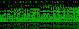
The display RAM needs to have some useful data in it, not just all-spaces which would be indistinguishable from the shift-register not working at all. Typically one might fill it with the values 0 to 255. This can be mimicked by simply having a fake display RAM with D0-7 outputs driven by the A0-7 inputs. If successful, the display should show this in text mode:
6847 character font
| The font ROM is slightly harder, since it will need
real data. The 6847 can use external font ROMs and we
could use one here, but of course it would require
programming a ROM, then wiring it to the FPGA. To avoid
this we can try implementing it inside the FPGA. Writing
a VHDL ROM is tedious but not complicated. It is possible
to write a program to create VHDL source from the binary
ROM data. Also time consuming. However, emulators have been written for the Atom and their source includes font ROM descriptions in assembler or C. Wouter Ras's emulator has source code available. These can be converted to VHDL using global search-and-replace in a text editor. The 5x7 font can be economically packed into 64 x7 bytes, but it is simpler for hardware reasons to space the characters at multiples of 8.Click here for rough draft VHDL. The ROM-defined pixels (light green) sit in the 8x12
character cell as shown on the right. |
|
6847 block-graphic font
The semigraphic modes also have a 'font' of sorts that could be defined in an 8x12 font ROM, but it is more efficient to control these with logic. These modes will be left for later.
3x2
cells
|
2x2
cells
|
1x4
cells
|
|||||||||||||||||||||||||||||||||||||||||||||||||||||||||||||||||||||||||||||||||
6847 colour palette
Colours on the 6847 are not wonderful, in fact they are pretty bad, but will need handling. Even a monochrome display will need the colours translating into grey levels. A real 6847 chip does not present RGB outputs (which would be very useful but require more pins than available). Instead it presents the colour information using two signals that are convenient for NTSC colour carrier modulation... but not PAL.
The video signals Y, CHA and CHB have 3 possible levels during the active display area: low, medium or high. Medium is about 1.5V. So extracting the RGB colour information from a real 6847 involves level comparators for the CHA, CHB signals then applying some boolean logic either through individual TTL gates or a small fast PROM.
| Voltages | A = 1 if CHA > 1.75 B = 1 if CHA < 1.25 C = 1 if CHB > 1.75 D = 1 if CHB < 1.25 |
|||||||||||
| COLOUR | Y | CHA | CHB | |||||||||
| Bin. | Name | A | B | C | D | R | G | B | Colour | |||
| 000 | Green | 0.58 | 1.0 | 1.0 | 0 | 0 | 0 | 0 | 0 | 1 | 0 | |
| 001 | Yellow | 0.48 | 1.5 | 1.0 | 0 | 1 | 0 | 0 | 1 | 1 | 0 | |
| 010 | Blue | 0.66 | 1.5 | 2.0 | 0 | 1 | 1 | 1 | 0 | 0 | 1 | |
| 011 | Red | 0.66 | 2.0 | 1.5 | 1 | 1 | 0 | 1 | 1 | 0 | 0 | |
| 100 | Buff | 0.48 | 1.5 | 1.5 | 0 | 1 | 0 | 1 | 1 | 1 | 1 | |
| 101 | Cyan | 0.58 | 1.0 | 1.5 | 0 | 0 | 0 | 1 | 0 | 1 | 1 | |
| 110 | Magenta | 0.58 | 2.0 | 2.0 | 1 | 1 | 1 | 1 | 1 | 0 | 1 | |
| 111 | Orange | 0.58 | 2.0 | 1.0 | 1 | 1 | 0 | 0 | 1 | 0 | 0 | |
| Black | 0.72 | 1.5 | 1.5 | 0 | 0 | 0 | 0 | 0 | 0 | 0 | ||
| The table above shows how the Acorn Atom colour board
handled colour translation. The RGB outputs were meant
for a TTL monitor with one bit per colour gun, so Orange
is approximated by Red, and Buff by White. With access to the internal logical colour values, we can avoid the analogue circuitry above and simply use a small look-up table like so: Orange can be made by having the Red signal at 100% and the green signal at 50%, so this could be achieved by having a half-intensity bit output for the Green signal. I'm not sure about what the colour 'buff' is, and suspect it is one of these naff colours that don't belong in a Real Hardware Engineer's wardrobe (along with puce, mauve, taupe and beige). I also suspect the original engineers were trying for white but did not manage to modulate the colour carrier amplitude (the colour saturation) completely down to zero. So they got it a bit wrong - white with a hint of red. White is a lot more useful. |
|
||||||||||||||||||||||||||||||||||||||||||||||||||||||||||||||||||||||
The colour palette is not programmable, though this might be a nice optional extra. The 6847 allowed limited colours by providing two extra analogue signals A and B, compatible with the colour modulation scheme of the NTSC TV standard, but not PAL. Acorn produced a PAL colour interface board that converted the Lum/ChrA/ChrB signals into TTL RGB and then into PAL compatible signals.
The colour handling varies between display modes. There are many details (refer to 6847 data sheet), but essentially the palette is fixed as 8 logical colours plus black.
The true graphics modes have only 2 bits / pixel so the CSS flag selects which group of 4 logical colours are used. These are usually the three primary colours (R,G,B).
The Acorn Atom colour board interprets buff as white, and orange as red. The latter simplifies the PAL colour carrier modulation circuitry.
An FPGA implementation is free to produce the RGB signals directly, for direct feed into a modern TV. The video RF modulation circuitry can be dispensed with. This also makes orange easier to obtain, by using 2 bits for the green gun.
Only the digital parts of the 6847 can be described in VHDL, synthesised and placed into the FPGA. The analogue circuitry must be a seperate module.
Shift registers
| 1 | C2 | C1 | C0 | L3 | L2 | L1 | L0 | -->1-bit to colour palette (four blocks in character cell) |
| C1 | C0 | L5 | L4 | L3 | L2 | L1 | L0 | -->1-bit to colour palette (six blocks in character cell) |
| d6 | d4 | d2 | d0 | -->2-bits to colour palette | ||||
| d7 | d5 | d3 | d1 | |||||
Implementation
First experiments were encouraging. The video signal was built up one step at a time. Milestones reached so far:
Graphics mode address sequencing is easy for adjusting the vertical resolution: a row of memory addresses are read once, twice or three times to produce pixels that are 1, 2 or 3 scan lines high. Horizontal resolution adjustment is less easy: the memory access rate may be halved to just 16 bytes per line. Multi-resolution shift registers involve quite a bit of internal multiplexing, and were the first candidate for putting into a ULA for the BBC micro.
Developing the colour graphics modes is a little tricky in that my PC TV card has no SCART connector (this is just too big!) so cannot take RGB direct. The input is either composite or S-video. Both of which require a modulated PAL colour carrier, something I would rather avoid. Monochrome display is not really adequate for debugging most graphics modes, because some colours have the same luminance.
However, text, semigraphics and 256x192 graphics are enough to get a basic Atom up and running. 256x192 is the highest resolution and the most useful graphics mode.
6847 Mode number encoding
| A/G | GM2:0 | D7 | D6 | X | Y | Colours | n | Cell height |
Mem size |
Atom mode |
CoCo V2:0 |
||
| 0 | 0 | 000 | 0 | 0 | 32 | 16 | Alphanumeric | 2 | 12 | 0K5 | 0 | 000 | |
| 0 | 1 | 32 | 16 | Alphanumeric inverted | 2 | 12 | 0K5 | 0 | |||||
| 1 | x | 64 | 32 | Semigraphic mode - 4 | 8 | 6 | 12 | 0K5 | 0 | ||||
| 1 | x | 64 | 48 | Semigraphic mode - 6 | 4 x 2 | 4 | 12 | 0K5 | 0 | ||||
| 1 | 0 | 001 | 1 | x | Undefined | ||||||||
| 2 | 0 | 010 | 1 | x | 64 | 64 | Semigraphic mode - 8. | 8 | 3 | 4 | 2K | 010 | |
| 3 | 0 | 011 | 1 | x | Undefined | ||||||||
| 4 | 0 | 100 | 1 | x | 64 | 96 | Semigraphic mode - 12. | 8 | 2 | 6 | 3K | 100 | |
| 5 | 0 | 101 | 1 | x | Undefined | ||||||||
| 6 | 0 | 110 | 1 | x | 64 | 192 | Semigraphic mode - 24. | 8 | 1 | 12 | 6K | 110 | |
| 7 | 0 | 111 | 1 | x | Undefined | ||||||||
| 8 | 1 | 000 | x | x | 64 | 64 | Graphics, colour | 4 x 2 | 3 | 4 | 1K | 1a | 001 |
| 9 | 1 | 001 | x | x | 128 | 64 | Graphics | 2 | 3 | 4 | 1K | 1 | |
| A | 1 | 010 | x | x | 128 | 64 | Graphics, colour | 2 x 4 | 3 | 4 | 2K | 2a | 010 |
| B | 1 | 011 | x | x | 128 | 96 | Graphics | 2 | 2 | 3 | 1K5 | 2 | 011 |
| C | 1 | 100 | x | x | 128 | 96 | Graphics, colour | 2 x 4 | 2 | 3 | 3K | 3a | 100 |
| D | 1 | 101 | x | x | 128 | 192 | Graphics | 2 | 1 | 2 | 3K | 3 | 101 |
| E | 1 | 110 | x | x | 128 | 192 | Graphics, colour | 2 x 4 | 1 | 2 | 6K | 4a | 110 |
| F | 1 | 111 | x | x | 256 | 192 | Graphics | 2 | 1 | 1 | 6K | 4 | 110 |
The semigraphics modes that require multiple accesses are shaded in purple in the table above. This is more complicated than the other modes, which use single-byte access to display data. These modes are available on the Tandy CoCo but not on the Atom. They read a new byte for each line in a character cell, the byte containing bits to select the colour of 'set' pixels, and bits to say which pixels are 'set'.
It is not clear what happens if you try to mix text and semigraphics in these modes - i.e. you don't keep d7 set in a character cell. Presumably the address sequencer puts out a row of addresses that repeat for n scan lines (where n = 192 scan lines / vertical pixels = 3, 2, 1 for semigraphic modes 8, 12, 24), and thus if d7 is not set the display will show a horizontal row from a character.
The 6847 data sheet does not mention semigraphic modes 8, 12, and 24 so one can assume they are new modes introduced by the 6883. The 6883's display mode register bits V2,1,0 control the video address sequencing. They almost correspond to GM2...0, except for V0 which differs in 64x64 and 256x192 modes.
In practice most software seems to use other modes, which are also far simpler from a software point of view.
| V 210 |
Div | Bits cleared by HS |
||
| X | Y | |||
| 000 | 1 | 12 | B4 to B1 | For text and semigraphics |
| 001 | 3 | 1 | B3 to B1 | I'm not sure about the 3. The 6847 data sheet says pixels can be 3 dot clocks wide but other data suggests it must be only 2 dot clocks wide. |
| 010 | 1 | 3 | B4 to B1 | |
| 011 | 2 | 1 | B3 to B1 | |
| 100 | 1 | 2 | B4 to B1 | |
| 101 | 1 | 1 | B3 to B1 | |
| 110 | 1 | 1 | B4 to B1 | |
| 111 | 1 | 1 | None (DMA) | |
The Y factor is the number of scan lines for which a row of
video memory addresses is repeated.
These are the graphic patterns expected with the test data.
All these patterns have been produced, including colours.
256x192 mode (GM=111) |
Pixels 1 scan line high 1 dot clocks wide |
|
128 x 192 (GM=101) |
128x192 mode (GM=110) |
Pixels 1 scan line high 2 dot clocks wide |
128x96 mode (GM=011) |
128x96 mode (GM=100) |
Pixels 2 scan lines high 2 dot clocks wide |
128x64 mode (GM=001) |
128x64 mode (GM=010) |
Pixels 3 scan line high 2 dot clocks wide |
64x64 mode (GM=000) |
Pixels 3 scan line high 4 dot clocks wide |
These modes have also been produced, but are not standard 6847 modes:
256x96 |
256x64 |