Acorn Atom Systeem by Kees van Oss.
Introduction:
Yes indeed, the original Acorn Atom still exists. I might be one of the few that still regularly do things with the Atom but I also want to give an impression about what can be done with the Atom.
However speaking about an ' original ' Atom. My Atom has been adapted during the years a lot of times and has
been extensively extended.
System:
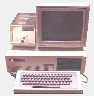
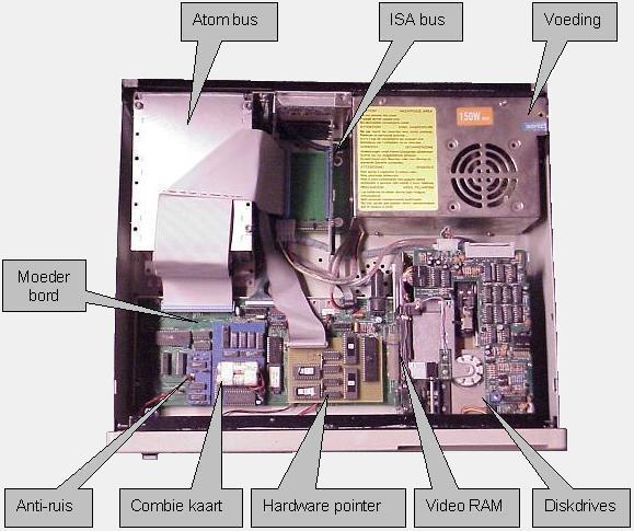
The system has two parts, the motherboard, cut in two parts, the keyboard part is placed in the original (shortened) cabinet and the CPU part is placed in an old PC cabinet. I did this to get space for the expansions. In the system the following components are found:
- Motherboard
- Keyboard
- Atom-bus, this is a frame in which original Atom expansion boards can be mounted
- ISA-bus, this is a PCB where onnectors are original PC expansion boards.
- 2 Disk drives.
- Power supply.
Motherboard:
On the original motherboard only the necessary components
have been fitted. Ever I bought a bare Motherboard and assembled it from start of only with
the most necessary components, no unnecessary address decoders
for the 2114's, no sockets for 2114's and no address decoder for the video memory. Some sockets are mounted to fit extension PCBs such as the combination-card, video-noise suppression and the hardware-pointer-card. These sockets provided the necessary I/O addresses.
I/O addresses not present on the sockets and proved nevertheless necessary were connected on legs from the sockets of which the purchased tracks were interrupted.
Because of this most PCBs have no wire connections and connectors which only jamming ensure. On the motherboard the next extensions are fitted:
Video RAM, this is an original Atomclub design replacing the six 2114 RAM chips on the motherboard with a single 8 K RAM chip. Hardware anti-noise supression, this PCB designed by
Peter Ehrlich has the CPU and VDU access memory half a CPU cycle out of phase. There are two advantages: firstly
the CPU and video processor are synchronized so that there is no noise to see on the screen, and secondly it
raises the CPU speed to 1.79 MHz instead of 1 MHz.
Combination card, this card carries several items such as a paging (#A000) card, a memory card and the 8th printer bit facility. Paging card, this contains paged memory, mapped at #A000. This consists of
four sockets of 32K EPROM, and two sockets of 8K RAM. Memory card, this is fitted with 32K battery-backed-up RAM at #0000 - # 7FFF. 8 th Printerbit, normally the Atom prints
only 7 bits because the 8th bit of the A-port is used somewhere else. This device passes on the 8th printer
bit to the printer port as a result of which can be printed normally nevertheless. 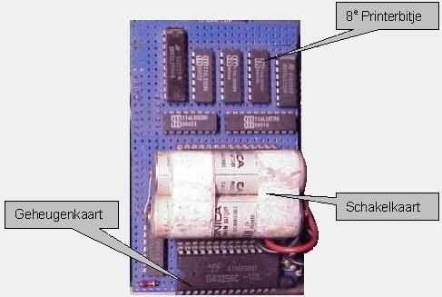
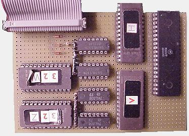
Hardware pointer, This circuit is also self-made and
works as follows: the circuit is situated between the video memory and the video processor and when the video
processor reads the data from the video memory, it finds on the print which address is read at the end. If on this
address a part of the mouse-pointer must be, then the print will treat the data so that the video processor
sees mouse-pointer instead of the original video memory dates. On the screen appears then mouse-pointer but the
memory contains still the original data. The circuit has two parts: 'mouse-pointer' and 'mouse-scroll' section.
The mouse-pointer section exists of two ROM's containing the data for 32 mouse pointers.
One ROM holds the 'white' information and the other holds the 'black' information. The 'white'
information becomes with a OR version and the ' black ' information with AND version added to the original video
data. This result is that only the pixels covered by the mouse-pointer becomes black or white.
The mouse-scroll section has two ROMs for moving the mouse-pointer, 1 for the horizontal - and 1 for the vertical scroll. These scrolling are actually nothing else then manipulating the video address lines. The video processor asks e.g. the data of address #8000, but gets the data of # 8020. Because of this it seems that the mouse-pointer has shifted up 1 line but in reality some address lines are 'rumbled '. The same in fact also happened to the horizontal shift but there has an extra trick applied because I wanted one bit scroll (1 pixel shift) and no byte scroll (8 pixels shift). The trick is that 8 pointers are defined, each shifted 1 pixel with respect to each other and the first 3 address lines (8 possibilities) stipulates which pointer must be shown there.
The result is a mouse-pointer moving on pixel level which does not change the data present on the screen and all this is done without software. The additional advantage is that this action works without any CPU speed reduction.
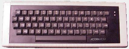
Toetsenbord:
The keyboard part , cut from the motherboard PCB, has been fitted
in the original Atom housing. Because the PCB is now much shorter I have also shortened the
housing. The keyboard data passes via 25-way D-type connector to the PC case in which the connector put
through the keyboard with keyboard-matrix the IC's.
Atom-bus:
This is a small 19 rack in which a number of standard Atom-bus
board can be fitted. The bus is an extension of PL6/7 bus of the original Atom.
In the rack the following cards are found:
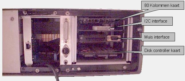
Disk controller card, this the original Acorn
disk interface based on the 8271. There are however
some adaptations done such as, moving the I/O address and
an 'open door' detection which gives correct error report
at a higher processor clock. 80 columns cardThis is the card developed
in the Atomclub with the 9345 video processor. It has
extra 40 or 80 column display modes.
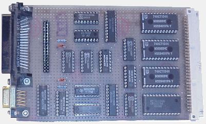
Mouse interface This self-developed design has 2
counters for respectively the X - and Y - position of the mouse which
can be read from the Atom. The mouse is a standard Amiga
mouse without intelligence, it only provides a
pulse trains through opto-couplers. The interface 'sees'
if the mouse moves left/right or up/down and the counter
concerned will increment or decrement. The interface also
has an extra 8-bit buffer in which the number of the
Mouse-icon (0-31) and keeps the on/off pointer state. On the print is a connector that
passed on the data of the counters and 8-bits the buffer
to the hardware pointer card.
I2C interface, this is a self-developed
PCB on which an I2C bus is fitted for connecting to
various I2C equipment. I2C is the bus developed by
Philips and still used inside TV's, video and audio
equipment.
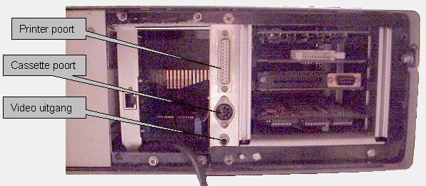
ISA-bus:
This
is a extension on PL6/7 in which standard PC extension
cards such as, a modem, serial/parallel I/O print card or
other can be fitted. The PC. I/O addresses of # 000-#3FF
is then projected in the Atom memory on # B400-#B7FF.
The data bus is 8-bits wide and this means that only
the older one plays cards 8-bits on I/O level can be
headed. In my Atom I have tested the following cards:
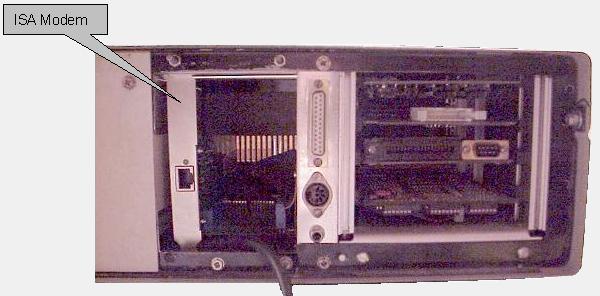
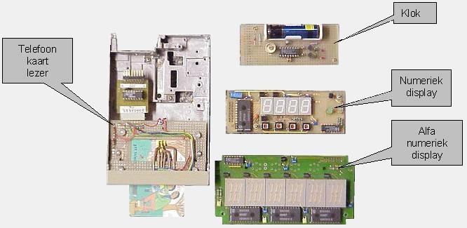
Modem card, one can make a telephone
connection with another PC or an Internet provider Serial I/O card, provides a com-port on the
Atom which has RS232 levels (+/- 12V) and is it works
simply to communicate with a PC for example. I use this
PCB to obtain access by means of a PC network
(purchasing power parities connection).
Diskdrives:
Two standard disdrives, 40 tracks single sided,
single density drives, meant for the original Acorn disc-controller.
Power supplies:
I had already replaced the standard Atom power supply by a PC PSU because this fit
better PC cabinet. An additional advantage was that when I fitted the ISA bus, the following supplies were already
present, + 5V, -5V, + 12V, -12V and GND.
|