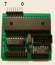
zoom.gif

AtoMMC2

An SD/MMC card interface for Acorn Atom computers by Charlie Robson (SirMorris).
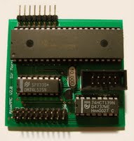
Introduction

AtoMMC2 provides modern mass storage for the classic British Atom computer. It is a combination hard/software solution designed to fit inside the Atom's case without unusual modifications to the machine. As of version 2.0 it provides full read and write access to files on a FAT formatted MMC or SD/SDHC card. It will work on any Atom computer as it doesn't require RAM, ROM or hardware expansions.

Read on or jump to:

Installation

The interface attaches to PL8, a 20 pin dual-row header on the Atom's mainboard. This header was not supplied with Atom kits nor was it fitted by default in production machines. It is a very simple job to fit, if required, but  take care to locate it pins up on the keyboard side of the main board, where the white outline is present, not on the component side. With the connector on the wrong side the pin ordering will be reversed and damage to Atom and interface will occur.

The header and interface are connected by the 20 way wire jumper. The interface connector can only fit one way and it would be awkward to fit the Atom end of the cable incorrectly but just in case please note the small triangle on the cable connector. This indicates pin 1. The location of pin 1 on PL8 is indicated by a small white dot on the Atom PCB.

The interface should be firmly mounted inside the Atom's case. This may be achieved by any method which will electrically/spacially insulate the interface from the Atom's main board. My recommendation is to put a 90 degree bend in the main cable and situate the interface on the base of the case, looping the cable over the right-hand edge of the PCB, avoiding the mounting hole.

'Servo tape', self-adhesive velcro strip or carpet tape are recommended fixatives. Care must be taken that the placement of the interface will not interfere with case fitting. The dongle may be tucked inside the case too if access to the card is not required or desired.

There are 2 available versions of the Atom firmware. One is configured as a service ROM and occupies the memory map in the utility ROM space of #A000->AFFF. The second is recommended for users of memory expansion systems with the ability to put code in the DOS ROM memory region at #E000. It requires two small patches to the Atom kernel ROM and naturally precludes the use of Atom DOS without appropriate ROM switching.

The A000 firmware.

This version resides in a 2532 EPROM and should be fitted in the socket marked IC24. Orientation is indicated by the notch in the chip's casing. It should be placed to match the chips around it. Please ensure that the EPROM's legs are not bent during fitting. If any do suffer an unexpected angular distortion, then straighten the affected pin(s) by placing the chip with its legs flat against a solid, flat surface. Gently press the bent leg back into alignment and try again. No damage should occur if the machine is powered up with a bent pin, but the software will fail.

In order for the code to initialise on reset it is necessary for the Atom to receive interrupts generated by the interface board. This may require the fitting of LK3 - a short wire link located to the right of PL8. Without this connection, or with interrupts disabled via configuration, the firmware will have to be initialised manually by typing the following after each reset:

LINK#AFCC

The E000 firmware.

Users of memory expansion boards should follow the procedure for burning the patched kernel and #E000 images into their system. The patched kernel will initialise the firmware at the right time and so no interrupts are needed. LK3 may be left unmade or interrupts can be disabled in the firmware. See the CFG command.

Initialisation

Once the interface and firmware are fitted the machine can be powered up and you should be greeted with a banner announcing the presence of the interface.

ACORN ATOM + ATOMMC2

Holding various keys when hitting BREAK will have effects:
  • CTRL will disable the interface firmware until next reset.
  • SHIFT will try to execute a file called MENU*
  • REPT will show additional information such as the firmware revision and type of card inserted.

* unless the meaning of the shift key on boot is inverted in configuration. See the CFG command.


This image shows what you should expect to see when holding REPT whilst resetting. The files on the card with a name beginning with the letter S are being catalogued.


Adding software to the card

Files are simply added to the card using your choice of operating system. Subdirectories are not supported.

The 'ATM' format is used to add required metadata to Atom files. It is a 22 byte header conforming to the following standard:

$00 - $0F : File name - Up-to 12 bytes of name + zero padding
$10 - $11 : Load address
$12 - $13 : Exec address
$14 - $15 : Length

Here's the header from Snapper showing the 22 header bytes and the first 10 characters of the main program:

53 4E 41 50 50 45 52 00 00 00 00 00 00 00 00 00   SNAPPER.........
00 29 86 CE 00 13 0D 00 00 52 45 4D 2F 2F 20 53   .).......REM// S

Firmware reference

All numeric parameters are specified in hex. No qualifiers such as # or $ are needed. Filenames being passed as parameters to '*' commands do not need quotes. The patched OS routines LOAD and SAVE require them. Optional parameters are shown in parenthesis.


To see a listing of the files on the card type

*CAT

at the prompt. You may abbreviate this command to *CA., *C. or simply *.

You may specify a wild-card character to filter the output. A single letter is supplied as a parameter and only files beginning with this character are displayed. 

Files with their DOS hidden attribute set are never shown. This is useful for hiding data files.

Press SHIFT or REPT to pause the listing. ESC will abort the listing.

*INFO filename

will show the metadata associated with a file. If none is present, junk will be printed. There is no way to know if data is present or not. You should see something like:

SNAPPER              2900 CE86 1300

This shows the load address to be #2900, its execution address to be #CE86 and the file lenth to be #1300 bytes.

*FATINFO filename

shows the raw filesystem information about the file. The first value is the file length in hex. Next is the start sector for the file. A reserved value of zero follows, then the attribute byte.

LOAD "filename"

will load the program into the currently selected text page.

*LOAD filename

will load the file into the location specified in its metadata.

*LO.filename (address)

will load the data into memory starting at the specified address. The star-command processor allows either quoted or non-quoted names to be used. The file's metadata is printed unless suppressed with the command *NOMON.

*RLOAD filename address

rawload will load the file from the card using the file system length rather than metadata information.

*RUN filename

or simply

*filename

will load and attempt to execute a program. The firmware attempts to run all programs even if they were not intended to be auto-running. In some cases this will produce an error in which case the sequence:

LOAD "filename"
RUN

should be used. Programs may also be loaded into the Atom by using:

*EXEC filename

This will present the file's content to the Atom as if it had been typed. Files read in this way should be ANSI text files such as a program like Notepad produces under Windows. This is a useful way of entering programs which only exist as listings.

SAVE "filename"

saves the current program. If the file already exists you will be prompted to overwrite it.

*SAVE filename start end (exec)

will save the specified block of memory. The end address is exclusive - in other words it is the address of the last byte to be written + 1. The execution address will be set to the start address if not specified.

*DELETE filename

will delete the specified file from the card. If you want to know what versions of the firmware you are running then typing:

*HELP

will tell you.

The remaining commands are related to the operation of the interface. A number of interface features are controlled through configuration bits. Typing

*CFG (value)

Will show the configuaration byte currently stored in EEPROM if no value is specified, else the interface's config will be changed. The default value is $FF. The following bits have an effect:
  • 5  ($20) - Enable Interrupts
  • 6  ($40) - Shift-Break Action
  • 7  ($80) - Enable Bootloader
Warning: Extreme care should be taken when changing the configuration bits. Certain combinations may have undesirable effects on the operation of the hardware. The most dangerous combination is disabling the bootloader when no firmware is flashed. This will result in an endless loop which cannot be aborted. The only way to reverse this action is to remove the PIC and use a dedicated PIC programmer to change the config bit.

Holding shift at boot-time will insert the string '*MENU' into the keyboard buffer and thus try to execute a program with that name. It may be desirable to have this done on every reset, and so you can invert the shift-key detection sense with bit 6. This way the menu is executed unless the shift key is held.


The user port

The interface features an 8-bit bidirectional user port - PortB. The data direction for each pinon the port is independent and user selectable. The directions and values are stored in EEPROM and will be restored on power-up.

*PBD (value)

will set the directions for each pin. 1 is 1nput, 0 is 0utput. FF will set all pins to input. 0 will set all to output.

*PBV (value)

will show or set the state of the PortB pins.

Setting the state of a line set as input will latch the value but otherwise have no effect. Reading the state of an output bit will show the value latched to that line. The port will sink way more than it can source, so I recommend using the port in open collector mode:- make the pin an input and tie the driven line high using a resistor. Change the port to output and drive it low in order to present a logic low level.

Here is a diagram showing the pin ordering on the board. The view is of the main interface PCB, top-left component side.


Users interested in using the interface firmware directly from an Atom program can check the 6502 source code for the Atom-side firmware.


Upgrading the firmware

The interface firmware may be upgraded using the built-in bootloader. The procedure is as follows:
  • Ensure the version of the firmware being flashed is compatible with the available Atom firmware.
  • Ensure the bootloader is enabled.
  • Obtain the latest PIC firmware files.
  • Format a card and copy the 3 firmware files to it.
  • Insert the card and reset the Atom.
  • The interface will light both LEDs and flash the green whilst the firmware is flashed.
  • The LEDs will extinguish. Remove the card and reset the Atom.
The bootloader is robust but there may be combinations of firmware updates which require further steps. Call your support representative for further assistance.

Troubleshooting

If no banner is shown at reset:
  A000 version: Check that interrupts are enabled
  E000 version: Ensure ROM is correctly loaded and that the kernel ROM os patched.

Solid green light on reset:
  Re-flash firmware.

CARD? error is shown when accessing the card:
  Try a different brand of MMC/SD/SDHC card.

No response from interface / card accesses hang:
  Ensure dongle connections are correct, ensure PL8 connection is correct.

Flames come from Atom case:
  Remove/bypass regulators and supply a healthy 5V.

Files/links

AtoMMC interface (by Charlie Robson)

  • Just for the fun a shot from the Prototype
  • Download PIC- + Atom software here
  • Example script file for a pic controller
  • Program to truncate files from WAD file (atmtrunc.zip)
  • Click here for the diagram and here for the printlayout
  • SDROM, filesystem ROM (by Kees van Oss):

  • Description and diagram interface SDROM v2.2 for atom VIA
  • Download SDROM2.2 (for Atom VIA interface)here
  • Download SDROM3.0 (for AtoMMC2 interface)here