|
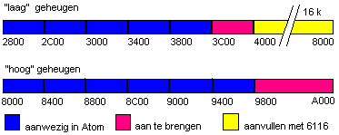
As an 8-bit's processor, the 6502 is able to address not more than 64K. In addition to the unavoidable (system) programs in Rom (Monitor (OS), Basic and Floating point) the ATOM has only 12K space available for Ram. As in many other computers, the ATOM can optionally be provided with additional Ram and or Rom. More than 64K can only be made available by double use of an available (block #Axxx) address, the so called bankswitching. Extensions are possible in static Ram, as the available 2114s, or in CMos Ram (6116 and 8416). In Cmos Ram the data can be secured by putting minimally +2 volt from a battery on the ICs after switching off the Atom.
So there are a number of possibilities to expand memory. Piggybacking* A memory expanding card, fi. the 16 K card released by the FAC. * Extending the present memory by piggybacking some KB of extra Ram. (the workspace with 1K up to 6K, the video-memory with 2K up to 8K)  Doing so, you will obtain an unbroken memory of 30K.
Piggybacking 6 Ram's 2114 on the "back" of the present 6 Ram's 2114, the ICs 32, 33, 34, 35 (high) en IC 10, 11 (low). All the pins from the ICs should be soldered on the corresponding ones from the bottom one; all pins except pin number 8, the Chip Select. All pins 8 from the top ones should be bent out a bit.
Insert now IC 10 and 11, each with a 'piggy', into the sockets. The bottom RAMs are able to do their job as usual. Make now a connection between the both pins number 8 from the top Rams and connect them with a wire with pin 7 from IC 6. This completes the low memory. Do the same with IC 32 and 33, again a 2114 on top of each other, all pins, except pin 8, connected to each other. After pushing back the ICs 32 en 33 you will have to connect the pins 8 from the two on top and make a connection with pin 1 of IC 30. Finally, do the same with IC 34 en 35, providing them with an extra 2114. After putting back the ICs 34 en 35, connect the two pins number 8 from the top 2114s with each other and connect the wire to pin 9 from IC 30. You now have got two memory blocks, a workspace of 6K (the text-pointer stays on #29) and a high memory block of 8K. All addresses to select the added Rams and the read/write lines are available on the mainboard. There is no need for drilling a hole in the mainboard for the connection-wires towards IC 30 pin 7 respectively pin 9. You may well solder that wire, with care, on the part from the pins that is sticking out of the socket. 
|